Choosing the Right Path for High-Frequency Waves
Radio-frequency (RF) signals do not move through a cable the way ordinary current does. Instead, the alternating current on the conductor sets up surrounding electric and magnetic fields, and those fields, rather than the current itself, carry the signal’s energy down the line. Because RF energy lives primarily in these fields, its behavior differs fundamentally from conventional low frequency and DC electricity, and the RF cables that guide it must be engineered with that distinction in mind.

There are three common cable types that are used for RF signal transmission:
- Coaxial (Coax) cable – A single center conductor surrounded by a dielectric, braided shield, and outer jacket.
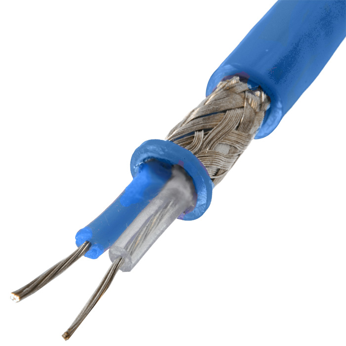
- Triaxial (Triax) cable – A coax core with an additional intermediate shield and insulation layer, giving a second return path that isolates sensitive signals or bias lines from ground noise.
- Twinaxial (Twinax) cable – Two balanced conductors twisted together inside a common shield.
Coaxial Cables for RF Signal Transmission
The most common configuration for RF signals is the coaxial (or coax) cable. Mechanically, the construction of a coax cable is simple. The central conductor of the cable is a wire of either stranded or solid construction, depending on the mechanical requirements and expected frequencies. This is surrounded by an electrically conductive shield, and the two are separated by an insulating layer known as the dielectric.

The dielectric’s job is quite different from ordinary insulation. It does not protect the cemter conductor from harm or from adjacent cables; instead, it shapes the cable’s electrical behaviour. In a coax cable, the dielectric is vital in controlling the relationship between the inner conductor and the shield. It ensures a precise separation of conductor and shield to control the impedance of the cable, which is also affected by the material from which the dielectric is formed.
The Impact of Impedance on Signal Quality
Impedance is the measure of how much the cable resists the flow of the alternating current. It is measured in ohms (Ω), the same unit used to measure conventional electrical resistance. Resistance explains only part of a coax’s impedance. Capacitance and inductance inside the structure dominate at RF frequencies.
The dielectric’s physical spacing and material properties determine the cable’s impedance. It creates the optimum physical separation between the conductor and the shield, and its permittivity governs the ease with which an electrical field can form inside it. Some materials used in dielectric construction include:
- Solid PE – economical, rugged, ~66 % velocity.
- Foamed PE – lighter, lower εr, reduced loss.
- PTFE (Teflon®) – microwave-stable, wide-temp.
- Expanded PTFE – porous, phase-stable, ultra-low loss.
- FEP – extrudable fluoropolymer, low-smoke.
- Air-spaced (ribbed) – mostly air; minimal attenuation.
The Effects of Capacitance and Inductance on Coaxial Systems
The two conductive surfaces of coax cables act as the plates of a capacitor, which causes energy to be stored within the cable. As the capacitance increases, more energy is retained within the cable, which slows the signal velocity and increases latency. Increased capacitance also contributes to energy loss and limits the bandwidth capabilities of the cable. Both effects become more dramatic with higher frequencies.
Inductance also plays a significant role in dictating the impedance of coax cables. It is the property of the conductor that opposes the change in current caused by a magnetic field. High-frequency signals depend on this magnetic field to transmit energy, and therefore information. A higher inductance leads to slower signal velocity.
There is no one “perfect” impedance for a coax cable. Rather, the precise impedance depends entirely on the requirements of the application.
Shielding the Signal from EMI
Our world is awash with radiation. Some is intentional, a byproduct of the vast number of radio transmissions upon which our modern world depends. Other radiation is unwanted, created by an array of sources, from faulty electrical devices to the background radiation of the natural world.
| Source | Type of Interference |
|---|---|
| Electromagnetic devices | EMI from power supplies, motors, and fluorescent lighting |
| Nearby wireless transmitters | RFI from Wi-Fi, Bluetooth, two-way radios, etc. |
| Solar activity | Solar flares and geomagnetic storms disrupting satellite and HF communication |
| Atmospheric noise | Broadband RF noise from lightning and weather, related events |
| Industrial machinery | High bursts of RF noise from welders, heavy motors, and switching devices |
Table 1: Major external EMI/RFI sources that can couple unwanted noise into coaxial cables, ranging from industrial power equipment to atmospheric and solar phenomena.
Any of these radiation sources can upset high-speed links. The coaxial shield helps block that unwanted energy. It works as a ground to carry away unwanted interference. The same shield also traps the cable’s own fields inside the jacket. That containment keeps the link from radiating noise into nearby circuits.
Triax Cables: An Additional Level of Security
However, there are applications in which even this level of protection is not sufficient. Adding a second shield boosts immunity and cuts leakage. It also provides an independent ground reference, eliminating the multiple return paths that create ground-loop currents.

The design of triaxial cable is intended to provide this protection. An additional conductive layer surrounds the core and inner shield, separated by a conventional insulating layer. While the more intricate construction of triaxial cable increases its cost, they are important solutions for superior signal integrity.
Reducing the Effects of Leakage Current with Triax Cables
In an ordinary coaxial cable, the signal conductor sits at some voltage while the outer shield is at ground. The plastic dielectric is never a perfect insulator. Its finite resistance, hundreds of mega-ohms to several giga-ohms, acts like a parasitic resistor across your measurement. The voltage across that resistor lets a small “leakage” current flow from the center conductor to the shield. Moisture, dirt, added length, and heat all drop that resistance. At pA or fA levels the resulting leakage can bury the true signal and delay settling.

Triax introduces a driven guard shield held at the same potential as the signal. That drops the dielectric voltage to zero, eliminating leakage. Any tiny residual current flows between the guard and the grounded outer shield, not through the measurement node.
You can learn more about eliminating leakage current with triax here.
Twinaxial Cable for High-Speed Data Applications
While coaxial and triaxial cables share many similarities, there is another cable configuration that is used in modern high-speed communication. Twinaxial cable, known as twinax, also shares certain features. Instead of a single conductor, it uses two parallel wires that are held in precise relationship to each other. Surrounding the pair is a dielectric and a single, common shield. In this cable, however, the dielectric’s role is not to maintain the relationship between conductor and shield. Instead, it governs the impedance between the two conductors.

Choosing the Right RF Cable by Starting with the Problem
The first step in determining the correct cable type is identifying the types of abuse the link will see, and which performance metric matters most. Once identify, the dominant design pressure, be it noise immunity, bandwidth, reach, or budget, the correct cable choice all but reveals itself.
Shielding & Ground-Loop Immunity
Stray electromagnetic fields, static discharge, and mismatched ground references can inject micro-volt errors or full-blown image artifacts into sensitive links.
In triax, a driven guard shield wraps the signal core. The guard is held at the same potential as the center conductor. With the field collapsed, leakage current vanishes, and ground-loop paths never form. The outer shield still ties to chassis ground, providing a second 360° Faraday cage. The result is lab-grade noise rejection for pico-amp instrumentation, HD broadcast camera feeds, and low-level medical sensors.
Signal-Integrity Bandwidth
High-speed serial lanes and broadband RF chains care less about absolute shielding and more about tight impedance control, crosstalk, and return loss.
Twinaxial – Inside twinax, the twisted pair stays balanced and low-skew. That geometry cancels common-mode noise. Those attributes make twinax ideal for 10–100 Gb Ethernet DACs, NVLink GPU links, and MIL-STD-1553 buses.
Coaxial – Coax keeps a stable 50 Ω or 75 Ω impedance from kilohertz IF stages up to microwave front-ends. That consistency makes it the default single-ended choice for broadband RF.
Link Distance & Attenuation
Every meter of copper and dielectric adds loss. The farther you need to go without active repeaters, the lower the cable’s attenuation must be.
Coax carries the distance load A solid conductor coax run can span tens of meters before attenuation or dispersion forces regeneration. Triax pays for its guard with a little extra loss. Twinax trades long reach for blistering differential bandwidth, so it shines inside a rack or on a bench.
Cost, Weight & Installation Practicalities
Large data centers, aircraft, and telecom huts can hold thousands of links. Every added gram or dollar multiplies fast.
Coax is a proven, commodity technology with the lowest cost-per-meter and the widest connector ecosystem.
Twinax uses less copper and dielectric than equal performance coax, keeping short-haul cloud links lightweight and inexpensive.
Triax is wider and pricier than the alternatives. Engineers reserve it for mission-critical, low-level signals where noise failures are costlier than the cable.
The Benefits of Optimal Cable Selection
Selecting the appropriate cable, whether coax, triax or twinax, depends on the compromise between cost, immunity to interference, and signal integrity. Coax cables offer simplicity and cost efficiency for a wide range of applications. Triax cables deliver superior noise protection where performance is important. Twinax cables, with their differential signalling, are ideal for ultra-fast data transmission over short distances in noise-sensitive environments.
| Design Pressure | Best-Fit Cable | Why It Matters | How the Cable Helps |
|---|---|---|---|
| Blocking external noise & preventing ground loops | Triaxial | Sensitive measurement, broadcast, and medical equipment can suffer micro-volt errors or image artifacts when stray fields couple into the line. | Two concentric shields give 360° isolation. The inner “guard” can be driven at signal potential, collapsing leakage currents and eliminating ground-loop paths. |
| Maintaining signal integrity & bandwidth | Twinaxial for differential, Coaxial for single-ended |
Digital links (QSFP, SATA, HDMI) and broadband RF chains demand tight impedance, low crosstalk, and minimal return loss. | Balanced twinax cancels common-mode noise and carries multi-gigabit NRZ/PAM4 traffic. Precision 50 Ω or 75 Ω coax handles wide-band RF with predictable loss. |
| Reaching required distance without regeneration | Coaxial (longest), Triaxial (moderate), Twinaxial (short hops) | Longer runs worsen attenuation; choose the construction that meets your link budget before adding active repeaters. | Solid single-ended coax has the lowest per-unit attenuation; triax adds minor extra loss for its guard; tightly coupled twinax sacrifices reach for high differential bandwidth. |
| Controlling material & installation cost | Coaxial (economical general purpose), Twinaxial (cheap for short links), Triaxial (premium) | Data centers and avionics racks may have thousands of links, every extra dollar or millimetre counts. | Standard coax hits most requirements at minimal cost. Short twinax jumpers save copper and weight. Triax, with its second shield and special connectors, costs and weighs more |
Table 2 - Matching cable construction to design pressures.
In today’s communication landscape, cable is critical. Coaxial, triaxial, and twinaxial cables each offer distinct advantages in signal integrity, resistance to interference, and cost. Understanding the differences ensures that engineers can provide optimal performance across many applications, from TV broadcasting to data centers. The right cable will deliver reliable, high-speed data transmission in today’s increasingly demanding environments.
Explore Cinch’s coax, twinax, and triax cable assemblies, and let Cinch help you meet the performance, budget, and environmental demands of your next RF project.
 Twinax and Triax Cable Assemblies
 RF and Microwave Cable Assemblies