Fiber optic cables are essential components in modern data transmission infrastructure. They support high-speed, interference-resistant communication and are particularly effective in applications that require high bandwidth, low latency, and strong signal integrity. Unlike traditional copper or wireless systems, fiber optics provide superior data security and immunity to electromagnetic interference (EMI).
The performance of a fiber optic system depends heavily on the physical and optical properties of its components. To understand and design reliable optical links, engineers must consider the construction of the cable, the behavior of light within the fiber, and key performance factors such as dispersion and attenuation. This paper examines these foundational principles and explains how they influence transmission quality, reliability, and system longevity.
How Fiber Optics Compare to Copper and Wireless Data Transfer
While fiber optics are now widely adopted for high-performance communication, it is important to understand how they differ from legacy technologies such as copper cabling and wireless systems. Each data transfer medium presents unique benefits and limitations that impact system design.
Copper cables, the traditional choice for electronic data transmission, are cost-effective and easy to implement. However, they are limited in bandwidth, prone to electromagnetic interference, and vulnerable to signal degradation over long distances. Additionally, physical security can be a concern, as copper pathways are more susceptible to signal tapping and crosstalk.
Wireless communication, whether based on ultrasound, radio frequencies like Bluetooth or Wi-Fi, or optical methods such as infrared, offers the advantage of cable-free deployment. These systems can support high-speed data transfer when using high-frequency carriers such as microwaves or lasers. Nonetheless, they introduce complexity in terms of design, cost, and reliability. Wireless systems are also subject to external interference and can be difficult to shield from eavesdropping.
Fiber optic systems address many of these limitations. They deliver higher bandwidth than copper and are less vulnerable to external noise or monitoring. However, like copper, fiber optics require a physical link between transmitter and receiver. This trade-off is offset by the superior performance characteristics that fiber optics provide, especially in secure, high-volume data environments.
| Feature / Characteristic | Fiber Optic Cable | Copper Cable | Wireless System |
|---|---|---|---|
| Bandwidth Capacity | Very high | Moderate | Variable (depends on frequency and protocol) |
| Signal Integrity | Excellent; immune to EMI and crosstalk | Susceptible to interference and degradation | Vulnerable to noise, fading, and obstruction |
| Distance Without Repeater | Long (>10 km typical) | Limited (100–500 m) | Typically, short to moderate (varies by technology) |
| Security | Difficult to tap or intercept | Easier to tap or interfere | Prone to interception if not encrypted |
| Physical Connection Required | Yes | Yes | No |
| Cost and Complexity | Moderate to high | Low | High (especially in secured or mission-critical use) |
| Installation and Maintenance | Requires careful handling and precise alignment | Simple and well-understood | Can be complex depending on environment |
| Typical Use Cases | Data centers, telecom, secure networks | Office LANs, short-haul data links | Mobile devices, remote sensors, temporary networks |
Table 1. Fiber optics vs copper vs wireless bandwidth, EMI immunity, security, and range factors for system architects.
Anatomy of a Fiber Optic Cable: Core, Cladding, and Coating
The performance of a fiber optic cable is determined largely by its internal structure, which consists of three main elements: the core, the cladding, and the buffer coating (also referred to as the outer jacket).
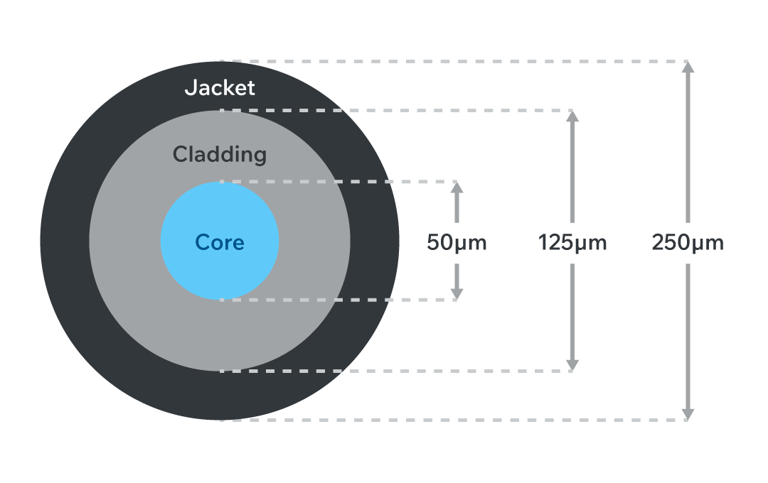
Figure 1. Cross-section of a 250 µm silica fiber showing 50 µm core, 125 µm cladding, and polymer buffer; core-cladding index step traps light by total internal reflection, delivering low-loss, EMI-immune data links for aerospace and defense systems.
Core: The core is the central region through which light signals travel. It is made from optically transparent glass or plastic with a high refractive index. Core diameters typically range from 5 µm to 10 µm for single-mode fibers and 50 µm to 65 µm for multimode fibers. The size and composition of the core directly affect light propagation, mode control, and signal attenuation.
Cladding: Surrounding the core, the cladding is made from material with a lower refractive index. This index differential enables total internal reflection, allowing light to remain confined within the core. The cladding typically has a standardized outer diameter of 125 µm, regardless of fiber type.
Buffer Coating (Outer Jacket): This protective layer adds mechanical strength and environmental resistance to the cable. It shields the internal fiber from moisture, abrasion, and physical stress during installation. The typical coated diameter is 250 µm (0.25 mm). In rugged environments or tactical applications, additional jackets or armor layers may be added.
Understanding the relationship between these components is essential for selecting or designing fiber optic systems that balance signal performance, durability, and installation flexibility.
Refractive Index and Light Confinement in Optical Fibers
The principle of light confinement in fiber optic cables relies on the concept of refraction. Refraction is the change in direction of a light wave as it passes from one medium to another and is described by Snell’s law (see equation 1, where i is the incident light wave and r is the refracted light wave). The refractive index (n) is a material property that characterizes this change compared to a vacuum and results from the fact that light travels more slowly in materials with higher refractive indices.
ni ⋅ sin(θi) = nr ⋅ sin(θr)
Equation 1
In a fiber optic cable, the core is engineered to have a slightly higher refractive index than the surrounding cladding. This difference enables a phenomenon known as total internal reflection. When light traveling through the core encounters the core-cladding boundary at an angle greater than the critical angle, it reflects back into the core instead of refracting into the cladding. The critical angle can be found by setting the angle of refraction to 90° and solving for the incident angle, which results in equation 2. This repeated reflection allows light to propagate along the length of the fiber with minimal signal loss.
θc = sin−1(nr / ni)
Equation 2
There are two main types of refractive index profiles in optical fibers:
Step-Index Fibers: These fibers feature a sharp boundary between the core and cladding. They are simple to manufacture but are more susceptible to modal dispersion, particularly in multimode configurations.
Graded-Index Fibers: In this design, the core’s refractive index gradually decreases from the center outward. This grading helps equalize the travel times of different light modes by increasing propagation speed at the edges, thereby reducing modal dispersion and improving bandwidth performance.
Precise control over refractive index is fundamental to optimizing signal fidelity and transmission distance in both single-mode and multimode fiber systems.
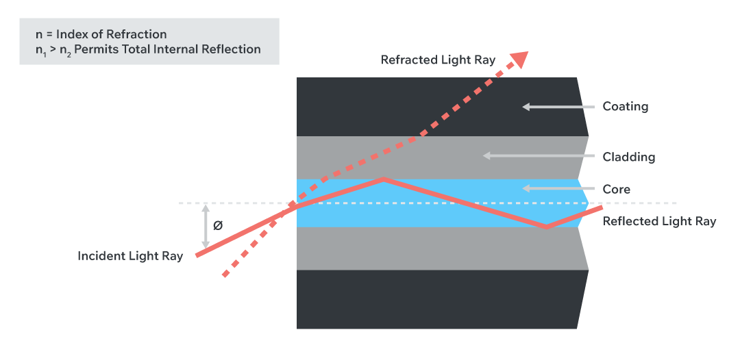
Figure 2. Total internal reflection path in step-index fiber showing core-cladding index difference that enables low-loss, high-bandwidth transmission.
The refractive indexes of the fiber optic cable core and cladding are selected such that the core has a higher index of refraction than that of the cladding. This difference in refractive indexes causes light from the core that impinges upon the interface at less than the critical angle to reflect back into the cable core. The core can either be constructed with a constant refractive across the cross section or with a graded refractive index. Graded refractive index cores are more expensive to construct but cause less dispersion in the data signal because the longer path length of the refracted light is mitigated by the faster speed of light transfer in the edges of the core than in the center of the core.
Single-Mode vs. Multi-Mode Fiber: Design and Application Differences
Fiber optic cables are categorized as either singlemode or multimode, depending on the diameter of the core and the number of light propagation paths, or modes they support. Selecting the appropriate type is critical for optimizing system cost, performance, and scalability.
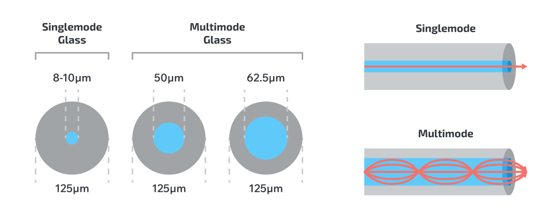
Figure 3. Single-mode (≈ 9 µm) vs multimode (50/62.5 µm) core sizes and modal paths - key design trade-offs for long-haul telecom versus rugged short-reach links.
Single-Mode Fiber (SMF)
Single-mode fiber features a narrow core diameter of approximately 5 µm to 10 µm, allowing only one propagation mode of light. This minimizes modal dispersion and enables data transmission over long distances with high fidelity. SMF typically uses edge-emitting lasers as light sources, which produce tightly focused beams suitable for narrow-core injection.
Because of its sensitivity to misalignment and contamination, single-mode fiber requires precise end-face preparation and connector quality. It is the preferred choice for long-haul telecommunications, metro networks, and high-speed data centers where maximum bandwidth and range are critical.
Multi-Mode Fiber (MMF)
Multi-mode fiber has a larger core diameter, usually 50 µm to 65 µm, supporting multiple light paths. This makes it more tolerant to connector alignment and contamination. MMF commonly uses LEDs or Vertical-Cavity Surface-Emitting Lasers (VCSELs) as light sources. These devices emit broader beams that excite multiple modes within the fiber.
While multi-mode systems are lower in cost and easier to install, they suffer from modal dispersion, which limits transmission distance and bandwidth. MMF is widely used in enterprise LANs, short-range communication, and industrial networks.
| Attribute | Single-Mode Fiber (SMF) | Multi-Mode Fiber (MMF) |
|---|---|---|
| Core Diameter | 5 µm to 10 µm | 50 µm to 65 µm |
| Light Source | Edge-emitting laser | LED or VCSEL |
| Modal Dispersion | Minimal | High |
| Distance Capability | Up to 100 km | Typically <2 km |
| Installation Complexity | High (requires precision) | Lower (easier alignment) |
| Typical Applications | Long-haul communication systems in aerospace, defense, and satellite networks | Rugged, short-range links in industrial, vehicle, and tactical environments |
Table 2. Single-mode vs multimode fiber specifications: core size, light source, dispersion, reach, and application fit.
Understanding Signal Dispersion in Optical Links
Dispersion is a critical factor in fiber optic system design because it directly impacts signal clarity, bit error rate (BER), and maximum transmission distance. Dispersion occurs when different components of a light signal travel at different speeds or paths, causing the signal to spread and distort.
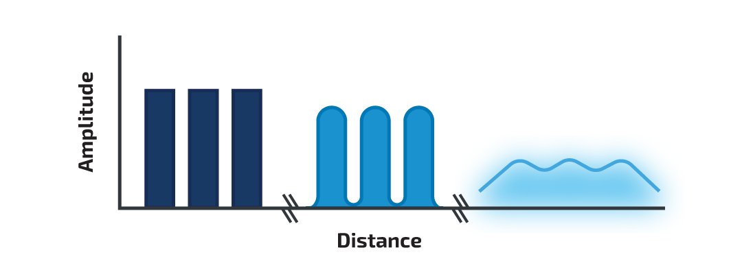
Figure 4. Dispersion-vs-distance curve with eye-diagram overlay illustrating BER degradation in high-speed fiber optic channels.
There are three primary types of dispersion in fiber optic systems:
Modal Dispersion: Modal dispersion arises in multimode fibers when multiple light paths (modes) arrive at the receiver at different times. This is common in step-index multimode fibers where higher-order modes travel longer distances within the core. Graded-index fiber mitigates this effect by allowing light to travel faster at the outer edges of the core, helping align arrival times. Modal dispersion is the main bandwidth limiter in multimode systems.
Chromatic Dispersion: Chromatic dispersion is caused by different wavelengths of light traveling at different speeds through the same material. Light sources such as LEDs, which emit a broad spectrum, are more susceptible to this effect. Narrow-spectrum sources like Distributed Feedback (DFB) lasers reduce chromatic dispersion and are preferred for high-speed or long-distance systems.
Polarization Mode Dispersion (PMD): PMD occurs when light with different polarizations propagates at different velocities due to imperfections or asymmetries in the fiber core. This is typically a concern in single-mode fibers used in high-speed or space-grade applications, where fiber stress or manufacturing inconsistencies introduce birefringence.
Visual Impact of Dispersion
The effect of dispersion can be visualized using an eye diagram. In a degraded signal, the eye "closes," indicating timing jitter and reduced receiver clarity. Modal and chromatic dispersion contribute to this closure, increasing the BER and reducing the maximum transmission rate.
Effectively managing dispersion is essential in mission-critical environments such as space communications, radar systems, and aerospace platforms, where signal precision and uptime are paramount.
Core Elements of a Link Budget
A link budget is the comprehensive accounting of all optical losses and gains in a fiber optic communication system. It determines whether a transmitted signal will reach the receiver with sufficient power to maintain a target bit error rate (BER). Accurate budgeting is essential for ensuring system reliability, especially in environments where maintenance access is limited, such as in aerospace, space, and military systems.
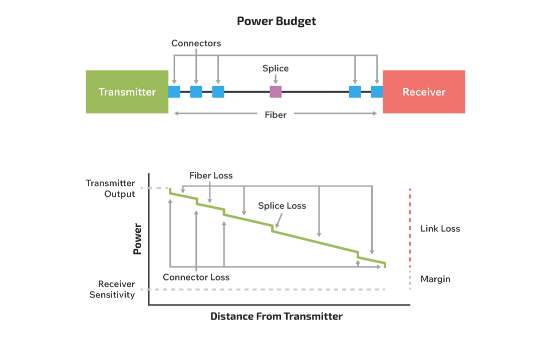
Figure 5. End-to-end optical link-budget map identifying splice, connector, and fiber attenuation contributions for mission-critical networks.
An effective optical link budget typically includes:
Transmitter Power Output (TX): The initial optical power emitted by the light source, usually specified in dBm.
Receiver Sensitivity (RX): The minimum optical power required at the receiver for reliable signal interpretation.
Fiber Attenuation: Signal loss due to absorption and scattering within the fiber, typically expressed in dB/km.
Connector and Splice Losses: Insertion loss introduced by each connection or fusion splice, typically 0.2~1 dB per point.
Margin Allowance: Additional buffer (usually 3–6 dB) to account for aging, temperature shifts, manufacturing tolerances, and field conditions.
Loss Mechanisms
Scattering Losses: Light that travels through silica encounters microscopic density fluctuations and geometric irregularities in the glass lattice. These discontinuities redirect a small portion of the beam in random directions, an effect known as Rayleigh scattering, whose magnitude rises steeply at shorter wavelengths (∝ λ⁻⁴).
For example, at only 100 m (about 328 ft) of fiber, attenuation at 850 nm is about 0.20 dB, whereas the same span at 1310 nm drops to 0.05 dB, illustrating how scattering-driven loss lessens as wavelength increases.
Although modern fibers exhibit baseline scattering of < 0.35 dB/km at 1310 nm, designers must still budget for additional penalties introduced by micro-bends and tight routing common in ruggedized harnesses. Minimizing sharp bends, specifying bend-insensitive fiber, and selecting longer operational wavelengths where practical are proven strategies for containing scattering losses.
Absorption Losses: Intrinsic absorption stems from trace dopants and hydroxyl (OH⁻) molecules left behind during fiber manufacture. These contaminants create distinct loss “water peaks” near 1000 nm, 1400 nm, and beyond 1600 nm, where vibrational resonances convert optical energy into heat.
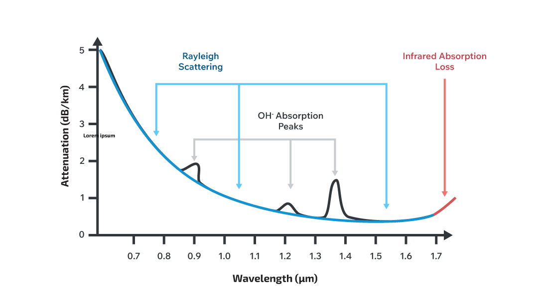
Figure 6. Spectral attenuation in silica fiber highlighting Rayleigh-scattering loss below 1 µm, discrete OH⁻ absorption peaks near 1.0 µm to 1.4 µm and rising infrared absorption beyond 1.6 µm.
To sidestep these troughs, commercial systems concentrate traffic in the 850 nm, 1310 nm, and 1550 nm windows, which sit between absorption bands and therefore offer the lowest baseline attenuation.
At 1 km and longer, choosing 1310 nm instead of 850 nm can reclaim several decibels of link margin, critical in aerospace or satellite payloads where optical power is at a premium. Engineers should also insist on low-water-peak (LWP) single-mode fiber for high-reliability links and verify supplier spectral-attenuation curves to confirm compliance with ITU-T G.652-D or equivalent standards.
Connector Contamination: Field studies indicate that more than 50% of optical-link failures originate from contaminated or damaged connector end faces, making cleanliness the single largest contributor to unexpected loss and reflections. Dust particles, fingerprint oils, and polishing scratches can raise insertion loss and return loss by 0.2 dB to 0.5 dB per mated pair, rapidly consuming the design margin in a tightly balanced link budget.
Engineers should adopt an inspect-before-connect workflow that meets the IEC 61300-3-35 pass/fail criteria, keep protective dust caps in place until final mating, and use single-use, lint-free cleaning tools or reel systems immediately before connection.
End faces on mission-critical links require 200x to 400x microscopy; any defects exceeding Zone A limits must be re-polished or the connector replaced. Consistent hygiene preserves optical power, minimizes back-reflections, and extends connector service life.
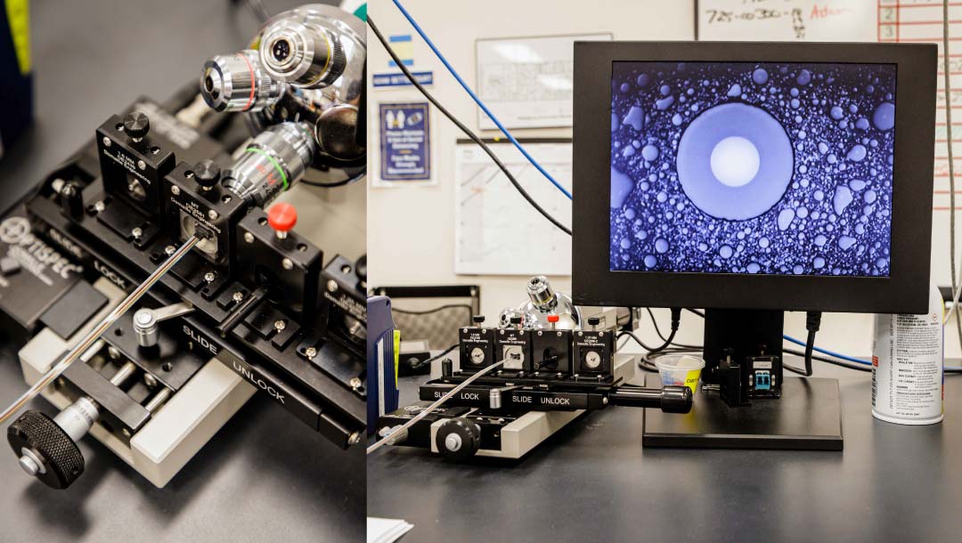
Figure 7. 200 × microscopic inspection station for fiber-connector end faces; an IEC 61300-3-35 pass/fail overlay flags dust, oil, or scratches so contaminants can be removed before high-reliability mating.
Best Practices for High-Reliability Links
-
Control Scattering with Thoughtful Routing and Wavelength Choice
- Route cables to respect the manufacturer’s minimum bend radius and avoid micro-bends that can add ≥0.1 dB per tight corner.
- When distance permits, operate at 1310 nm or 1550 nm rather than 850 nm; the longer wavelengths incur one-quarter of the Rayleigh-scattering loss observed at 850 nm.
-
Mitigate Absorption by Avoiding Water-Peak Regions
- Specify low-water-peak (LWP) single-mode fiber compliant with ITU-T G.652-D for links that traverse humid or high-altitude environments.
- Keep traffic within the 850 nm, 1310 nm, or 1550 nm windows to sidestep OH⁻ absorption bands and preserve several decibels of margin at kilometer scales.
-
Eliminate Connector Contamination Before Mating
- Enforce an “inspect-before-connect” protocol that follows IEC 61300-3-35 criteria; any end face failing Zone A limits must be cleaned or re-polished.
- Use sealed dust caps during handling, and clean with single-use, lint-free tools immediately prior to mating; contamination can cost 0.2 dB to 0.5 dB per connector pair.
-
Favor Fusion Splicing over Connectors in Shock or Vibration Prone Assemblies
- Fusion joints add <0.05 dB and remove two contamination points, enhancing long-term stability in aerospace, defense, and industrial deployments.
-
Select Fiber and Light Source as a Matched Pair
- Pair VCSELs with OM3/OM4 multimode fiber for 10 Gb/s to 25 Gb/s links ≤500 m.
- Use edge-emitting DFB lasers with single-mode fiber for ranges beyond 10 km or where chromatic dispersion targets are stringent.
-
Validate Link Budget Against Worst-Case Conditions
- Include ageing, temperature, and maintenance allowances (≥3 dB combined).
- Verify bit-error-rate (BER) ≤1 × 10⁻¹² with a PRBS 2⁷–1 pattern before release.
-
Document and Monitor Service-Life Stressors
- Track cumulative bending, connector mating cycles, and environmental exposure in maintenance logs.
- Trigger proactive replacement before performance degradation.
A robust link budget ensures that signal degradation remains within acceptable limits throughout the lifecycle of the fiber optic system, enabling long-term reliability and minimal maintenance in demanding conditions.
Light Sources for Fiber Optics: LED, VCSEL, and LASER Compared
The choice of light source significantly influences the performance, cost, and distance capabilities of a fiber optic system. The three primary types used in commercial and high-reliability applications are LEDs, VCSELs, and edge-emitting lasers. Each source has distinct optical characteristics suited for specific fiber types and transmission requirements.
Light Emitting Diodes (LEDs)
LEDs are the most economical option and are typically used with multimode fibers for short-range applications. They emit a wide, divergent beam with broad spectral content, leading to higher modal and chromatic dispersion. As a result, LED-based systems are limited to low data rates (≤1 Gb/s) and short distances (≤100 meters).
- Typical Wavelengths: 850 nm, 1300 nm
- Advantages: Low cost, simple drive electronics
- Limitations: Low coupling efficiency, high dispersion, limited bandwidth
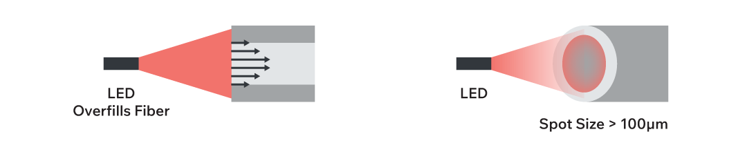
Figure 8. Diagram showing how a wide light beam from an LED overfills a multimode fiber, increasing modal dispersion
Vertical Cavity Surface Emitting Lasers (VCSELs)
VCSELs offer a balance between performance and cost. These devices emit a more focused beam than LEDs and operate efficiently with multimode fibers in high-speed, short- to medium-range links. VCSELs are widely used in data centers, industrial networks, and aerospace subsystems where compactness and moderate range are key.
- Typical Wavelength: 850 nm
- Advantages: Higher output power than LEDs, lower cost than edge-emitting lasers, good bandwidth-distance product
- Limitations: Limited to multimode fibers; not suitable for long-haul links
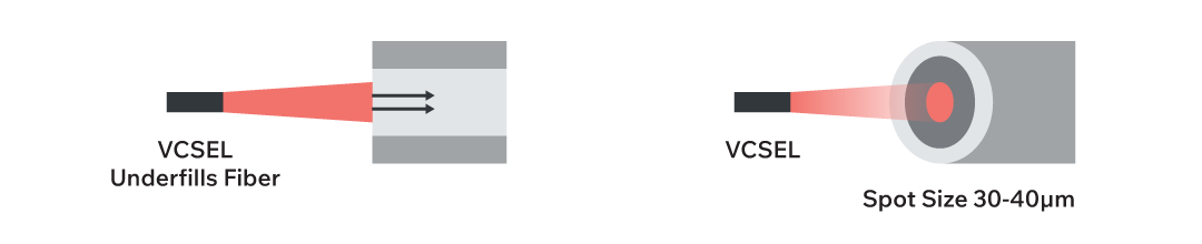
Figure 9. Visualization of a VCSEL’s focused beam entering a multimode fiber with better mode control than an LED.
Edge-Emitting Lasers (e.g., DFB Lasers)
Edge-emitting lasers, including Distributed Feedback (DFB) lasers, provide high power and a narrow spectral output, making them ideal for single-mode fiber systems. These lasers are required for long-distance, high-speed communication links, especially in telecommunications, defense, space, and satellite systems.
- Typical Wavelengths: 1310 nm, 1550 nm
- Advantages: High power, low spectral and modal dispersion, long-range capability
- Limitations: High cost, sensitive to back-reflection, precision alignment required
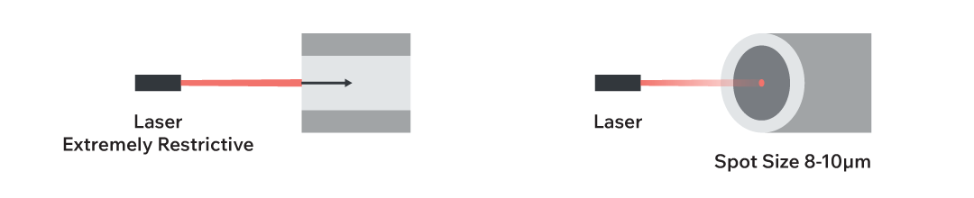
Figure 10. Graphic showing a laser’s narrow beam coupling into a single-mode fiber, illustrating the precision required.
Choosing the right light source involves balancing distance, data rate, environmental constraints, and cost, especially in Cinch's core markets, where ruggedization and performance reliability are critical.
For high-speed digital optics, designers should also verify the extinction ratio (ER), the logarithmic power difference between the laser’s ‘1’ and ‘0’ states, because an ER of ≥ 3 dB is assumed in IEEE 802.3 10 GbE and above. Insufficient ER reduces eye-opening and can nullify the link-margin gains obtained from lower fiber attenuation or improved OMA.
| Light Source | Fiber Type | Range | Data Rate | Typical Use Cases |
|---|---|---|---|---|
| LED | Multimode | ≤100 m | ≤1 Gb/s | Low-cost links, industrial automation |
| VCSEL | Multimode | ≤500 m | Up to 25 Gb/s | Data centers, aerospace avionics, harsh environments |
| DFB Laser | Single-mode | ≥10 km | 10 Gb/s to 100+ Gb/s | Telecom, satellite, defense, long-haul backbones |
Table 3. LED, VCSEL, and DFB-laser characteristics—wavelength, bandwidth-distance limits, and target use-cases.
OM Fiber Standards: Matching Cable Types to Bandwidth and Distance Needs
Multimode optical fibers are classified into standardized categories known as Optical Multimode (OM) designations, which define the bandwidth-distance performance of the cable. These standards are critical for ensuring compatibility with high-speed communication protocols such as Ethernet, Fibre Channel, and InfiniBand.
The OM classification ranges from OM1 through OM5, with each generation offering improved modal bandwidth and distance capabilities, particularly when paired with laser-optimized light sources like VCSELs.
| OM Type | Core Diameter | Typical Light Source | Modal Bandwidth @ 850 nm | Max Distance (10 GbE, VCSEL) | Example Applications |
|---|---|---|---|---|---|
| OM1 | 62.5 µm | LED | 200 MHz·km | ~33 m | Legacy aircraft wiring, retrofit in military facilities |
| OM2 | 50 µm | LED | 500 MHz·km | ~82 m | Industrial controls, short-run test platforms |
| OM3 | 50 µm | VCSEL | 2000 MHz·km | 300 m | Embedded comms in defense vehicles, shipboard LANs |
| OM4 | 50 µm | VCSEL | 4700 MHz·km | 400~550 m | High-speed avionics, aerospace-grade networking systems |
| OM5 | 50 µm | VCSEL (SWDM) | 4700 MHz·km | ≥ 550 m | Space-grade comms, next-gen mission control backbones |
Table 4. OM1-OM5 multimode standards—modal bandwidth, VCSEL reach, and recommended aerospace/industrial applications.
Understanding these standards is essential when specifying cable assemblies or system designs to meet current and future bandwidth demands, particularly in mission-critical or space-constrained applications.
Selection Guidelines
Match speed and reach first
- ≤1 Gb/s, ≤100 m → OM1.
- ≤10 Gb/s, ≤82 m → OM2.
- 10 / 25 GbE, ≤300 m → OM3.
- 40 / 100 GbE SR4, ≤550 m → OM4.
- 100 GbE SR-SWDM4 or 400 GbE, ≥550 m → OM5.
Audit the installed fiber plant
- Design to the lowest OM grade already in place.
- Verify connector style (LC, SC, MIL-38999) before specifying upgrades.
Future-proof where practical
- If a platform roadmap calls for ≥2× speed growth within five years, choose OM4 or OM5 now to avoid later recabling.
Account for environmental stresses
- Tight bends or high vibration → bend-insensitive OM3/OM4.
- Extreme temperature or radiation → MIL-qualified OM4.
Pair the light source with the fiber
- Use VCSELs on OM3–OM5.
- Reserve OM5 for SWDM transceivers that operate from 850 nm to 950 nm.
- Avoid LED overfill on OM3+ to minimize modal noise.
Budget connector loss and cleanliness
- Allocate ≥0.3 dB per mated pair.
- Enforce an inspect-before-connect workflow to prevent contamination from eroding link margin.
Design Takeaways for Fiber Optic Engineers
A comprehensive understanding of fiber optic cable fundamentals is essential for engineers designing communication systems in high-reliability environments such as aerospace, defense, industrial automation, and space systems. As this paper has demonstrated, the structure of a fiber optic cable, from core to coating, directly affects signal containment, mechanical durability, and installation performance. Selecting between single-mode and multimode fiber requires careful consideration of transmission distance, bandwidth requirements, and alignment tolerances, with each configuration offering distinct trade-offs. To translate that theory into practice, keep the following design rules front and center:
- Engineer from the glass up – core, cladding, and buffer design dictate signal confinement, mechanical strength, and EMI immunity in high-reliability aerospace, defense, and industrial fibers.
- Pick the right pipe – deploy single-mode fiber (SMF) + DFB laser for >10 km / 100 Gb/s links; choose OM3-OM5 multimode fiber (MMF) + VCSEL for ≤550 m backbones where cost and connector tolerance rule.
- Tame dispersion & attenuation – select bend-insensitive OM4/OM5, maintain minimum bend radius, and route to control modal, chromatic, and polarization dispersion that drive bit-error rates.
- Build a bullet-proof link budget – include fiber loss, ≥0.3 dB per connector, and worst-case temperature/radiation; confirm extinction ratio ≥3 dB and adequate optical modulation amplitude (OMA) to secure BER ≤1 × 10⁻¹².
- Inspect-before-connect – enforce fiber end-face cleaning to eliminate the 0.2 dB to 0.5 dB penalties that cause more than half of field failures.
- Follow the OM roadmap – OM3 for 10/25 GbE, OM4 for 40/100 GbE SR4, OM5 + SWDM for 100/400 GbE; this future-proofs throughput while staying backward-compatible.
- Leverage Cinch’s portfolio – ruggedized cables, expanded-beam connectors, and radiation-tolerant transceivers keep mission-critical fiber links online wherever you deploy.
Master these principles and you will deliver long-lived, low-maintenance fiber networks that meet the toughest aerospace, defense, industrial, and space-grade requirements, exactly the environments Cinch Connectivity Solutions was built to serve. When you are ready to turn designs into hardware, explore Cinch’s complete line of rugged fiber-optic cables, connectors, and transceivers engineered for extreme conditions.
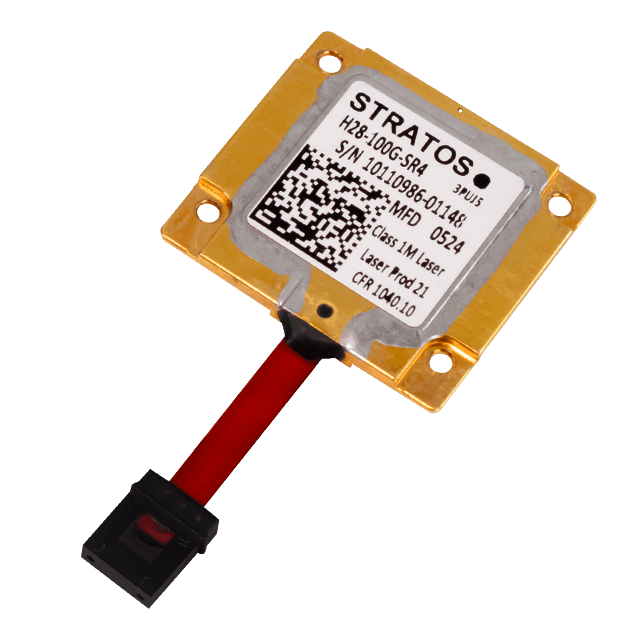 Optical Transceivers
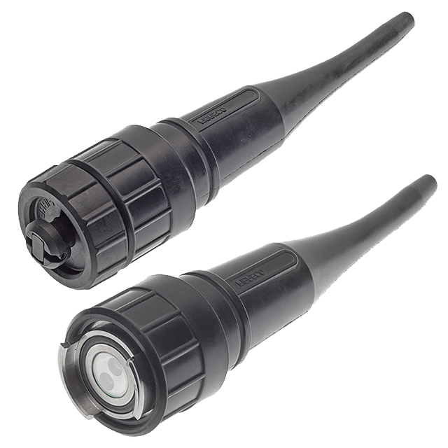 Expanded Beam Connectors
 Media Converters