The Shift to High-Speed Optical Links in Aerospace Systems
As aerospace and defense platforms continue to evolve, so do their data communication needs. Traditional avionics buses like MIL-STD-1553, while robust and deterministic, are limited to low data rates and are insufficient for high-bandwidth applications such as radar, real-time video, and high-speed sensor data. To meet these demands, modern systems increasingly adopt ethernet-based fiber optic links, many of which are standardized under the IEEE 802.3 family. These standards define data rates from 1 Gbps up to 400 Gbps and include advanced modulation schemes such as NRZ and PAM4, as well as built-in Forward Error Correction (FEC) mechanisms to ensure signal integrity. As data rates rise and system noise becomes harder to mitigate through hardware alone, FEC has become an essential tool for achieving the low bit error rates required in mission-critical environments. This paper explores the principles of FEC, the trade-offs involved in its implementation, and its specific applications within high-speed fiber optic links in aerospace systems.
Signal Integrity Challenges in High-Speed Data Transmission
In systems where information is transmitted, both the desired signal and unwanted noise are present. The signal carries the intended information, while noise introduces interference that can hinder accurate reception. The balance between these two elements is often measured using the signal-to-noise ratio (SNR), which quantifies the relative strength of the signal compared to the noise. SNR is typically measured in decibels (dB) and can be calculated as shown in equation 1.
SNR (dB) = 10 · log10 (Psignal / Pnoise)
Equation 1: Signal-to-Noise Ratio (SNR)
When noise is sufficiently low (resulting in a high SNR), the data can be received with the accuracy needed to meet the system's requirements. Conversely, if the noise level is too high (leading to a low SNR), the data may become corrupted and unusable.
For example, in a traffic density measurement system, it may be acceptable to have errors in detecting the number of vehicles by as much as 5% or 10%. In contrast, a railway traffic detector controlling a crossing gate should accurately detect the presence of an oncoming train with an error rate of 0.0001% (1 PPM).
Many methods have been developed to improve the SNR of a system. This includes changes in the hardware, the software, or the data itself. In this paper we will discuss the method known as Forward Error Correction (FEC) whereby extra bits are added to the stream of digital data to enable error detection and error correction.
Error Detection and Correction Methods
When transmitting digital data, the system designer has many options to choose from regarding data manipulation to detect and correct errors caused by noise in the data stream. The system designer may choose to transmit the data and add no error detection or correction provisions. This choice adds no cost or data transfer latency to the system but offers no improvement to the SNR of the system data transfer. A second option is for the system designer to implement error detection; in the form of parity, checksum, or cyclic redundancy check (CRC) bits. These are all low cost, low latency methods to detect errors in the data stream, but they do not provide the ability to recover the original data if the received data is corrupted.
| Method | Behavior | Performance Tradeoffs |
|---|---|---|
| Parity | Adds a single bit to indicate if the total number of 1s is even or odd. | Low cost and low latency, quickly detects single-bit errors. Cannot correct errors; limited to detecting only an odd number of bit errors. |
| Checksum | Calculates a sum of data segments and appends it to the data stream. | Good for detecting random errors and verifying data integrity. No error correction capability; performance depends on checksum algorithm complexity. |
| CRC (Cyclic Redundancy Check) | Generates a short, fixed-size checksum from a polynomial division of data. | High detection capability for burst errors; widely used in networks. Cannot correct errors; more computationally intensive than parity or simple checksums. |
| FEC (Forward Error Correction) | Adds redundant data to allow both error detection and correction at the receiver. | Provides the best performance in noisy channels. Increases data transfer latency, hardware, and software complexity; higher implementation cost. |
Table 1: Comparison of various error detection methods
A third method is to implement FEC, which can both detect and correct errors in the received data stream. Implementing FEC will provide the most benefit but can be the most expensive in terms of hardware, software, and data latency.
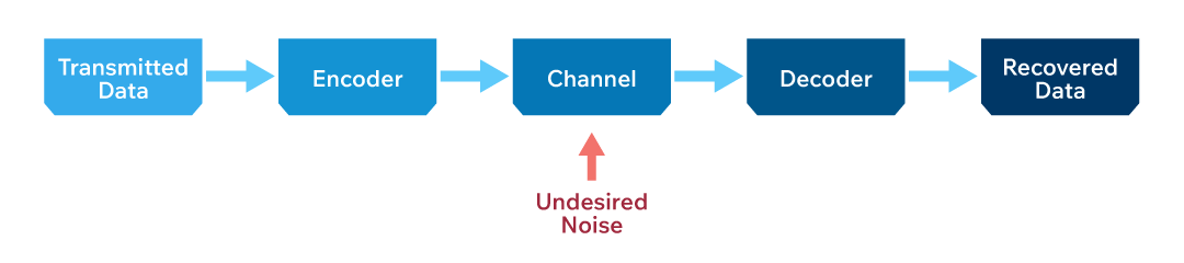
Figure 1 shows a data transfer path with undesired noise present in the data communication channel. The encoder and decoder blocks in the diagram accomplish the error detection, or detection and correction, but potentially add to the system's cost and data transfer latency.
Latency Considerations in FEC-Coded Fiber Links
The Reed Solomon coding is a standard FEC method used in high-speed optical networks, specifically RS (255, 239) which indicates there are 255 symbols per data block: 239 information symbols and 16 parity symbols. This coding scheme can correct 8 random errors per data block. The RS (255, 239) encoding adds 6.3% symbol overhead to the data stream (239/255 = 93.7% data, 6.3% overhead) which means that the codeword transfer rate must increase by 6.3% to maintain the original information symbol transfer rate.
Depending upon the capabilities of the data transfer system, the designer can either increase the overall data transfer rate by 6.3% to compensate for the overhead bits or accept the reduced information symbol transfer speed. For block encoding/decoding techniques, such as Reed Solomon, latency will be added by the need for the encoder and decoder to process an integer number of codeword blocks in the data stream. For Reed Solomon encoding, an entire block of information symbols must be buffered before the parity symbols can be calculated and added. Conversely, on the receiver side, an entire block of information symbols and parity symbols must be received before the error correction decoding process can begin.
In many cases, the total latency of encoding and decoding can be on the order of 2n or 3n (n is block size). As an example, a 10 Gbps link with RS (255,239) FEC may have added latency of 1 µs, which is the equivalent of about 300 meters of fiber optic cable propagation delay. If the same RS (255,239) FEC is implemented in a 1 Gbps link, the added latency would be around 10 µs, which is equivalent to about 3 km of optical fiber cable delay.
While FEC implementation can lead to increased system costs and data latency, it also has several advantages, such as improving Bit Error Rate (BER) by several orders of magnitude. Typical links see improvement in bit error rates from 10-4 to 10-12 or better when FEC is employed.
Evaluating BER Performance
The graph in Figure 2 shows the BER versus E/N ratio for a raw uncoded data stream and data streams with different error detection and correction coding. In the E/N ratio, E represents the energy per bit and N represents the noise spectral density in a 1 Hz bandwidth, thus the E/N ratio is a representation of the SNR for the data stream. The graph shows the performance and overhead rates for uncoded data and for several different types of FEC coding. The RS(255,239) coding is notated as RS-8 in the graph.
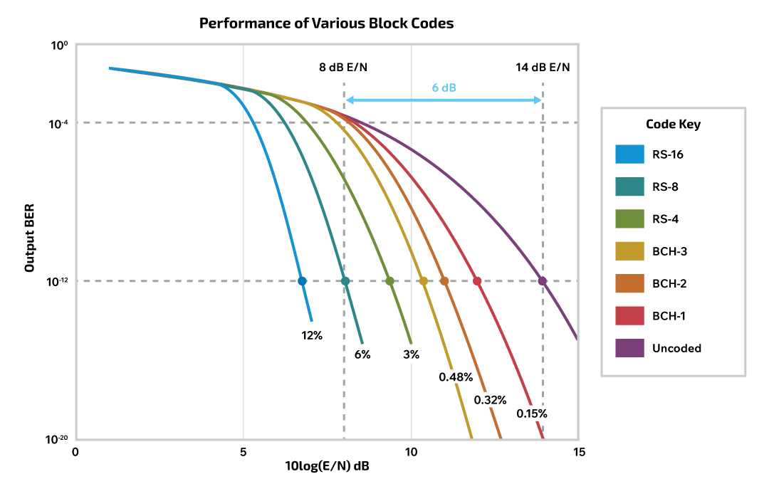
As we can see from the graph that implementing RS (255,239) FEC code will improve the BER from 10-4 to 10-12 at an E/N ratio of 8 dB. This is a 6 dB E/N improvement from the uncoded case, where E/N has to be 14 dB to achieve the BER 10-12 performance.
System Architecture and Noise Considerations in Fiber Links
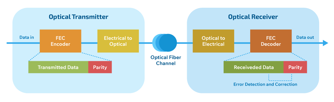
A block diagram of an optical fiber data transfer system implemented with FEC coding is shown in Figure 3. On the transmit side, error-free data is presented to the FEC encoder and coded data including parity symbols are routed to the optical transmitter circuit. The system assumes a clean coded data stream to the optical transmitter. Noise-induced errors can occur in the system as the data is converted to optical signals, during propagation through the fiber channel, or during the optical receive conversion process before being presented to the FEC decoder. Dominant noise contributors for the system are the PIN diode and receiver amplifier in the optical receiver block. Additional contributors to the system noise can be experienced, such as sampling time offset and jitter in the A/D converter in the optical receiver block, bandwidth limits of both active and passive elements between the output of the encoder and the input to the decoder, and imperfect laser modulation characteristics in the optical transmitter. Examples of laser modulation characteristics that may contribute noise include modulation timing jitter and degraded extinction ratio (ER) of the laser. In laser applications, the ER of a laser describes the ratio between the on and off power levels, and low ER levels reduce the margin for detecting signal on versus signal off.
The concept of using FEC for optical networks is not new. The nature of the data transferred over the optical channels often requires SNR improvements such as that which FEC coding contributes. High-speed optical data transfer networks used in under-sea communication cables have utilized FEC since the mid-1990s. More recent applications for FEC coding are found in fiber optic data transfer systems in military aircraft. In these systems, the data rates are between 1 and 25 Gbps and the fiber optic cable length is 30 meters or less. In many applications, the optical signal is created with a semiconductor laser diode and a PIN diode is used as the optical detector. The SNR of these aircraft optical data transfer systems is affected by various noise sources and other artifacts. The following are some of the potential noise sources in the optical system.
| Component | Noise Source | Impact on System |
|---|---|---|
| Optical Transmitter | Laser modulation timing jitter | Affects modulator clock stability |
| Laser modulation ER | Impacts differentiation of optical signal logic levels | |
| Inter-symbol Interference (ISI) | Causes timing and non-linearity issues in electrical to optical circuits | |
| Bandwidth of electronic components post-FEC encoder | Limits data transfer rate and signal integrity | |
| Fiber Optic Cable and Connectors | Optical channel cross talk (multi-fiber/WDM systems) | Reduces signal clarity through interference |
| Bandwidth or losses (long cable lengths) | Leads to signal degradation and increased attenuation | |
| Optical Receiver | Photodetector (e.g., PIN diode) | Corrupts the analog signal between photodetector and amplifier |
| Photodetector amplifier | Introduces noise in the signal between amplifier and A/D converter | |
| Hard decision threshold ambiguity | Caused by A/D clock stability and threshold detection errors | |
| Sampling time offset and jitter | Reduces accuracy of A/D converter sampling | |
| Inter-symbol Interference (ISI) | Affects timing and non-linearity in optical to electrical conversion | |
| Bandwidth of components pre-FEC decoder | Limits performance and data recovery capabilities |
Table 2: Common noise source in fiberoptic communication
Receiver Sensitivity and Loss of Signal
In applications where the optical fiber length is short and the laser characteristics are clean, such as in many aircraft, the SNR is dominated by photodetector and amplifier noise which is experienced at low received signal powers, as when link performance is limited by the optical connector attenuation losses. For these applications, measuring BER against receiver (RX) sensitivity is a more practical performance metric than BER against SNR.
RX sensitivity is calculated based on the diode responsivity and input-referred RMS noise to achieve a given BER. It should be noted that while SNR is a ratio of power levels, and thus the formula to convert the power ratio to dB is 10log10(SNR), the RX sensitivity is a ratio of voltages and thus the formula to convert the voltage ratio to dB is 20log10(RX sensitivity). This difference causes the RX sensitivity curve to be twice as steep as the SNR curve and thus the FEC coding gain is 2.5 dB of RX sensitivity as compared to 5 dB of SNR.
Voltage Ratio (dB) = 20 · log10 (Vreference / Vsignal)
Equation 2: Voltage Ratio in dB
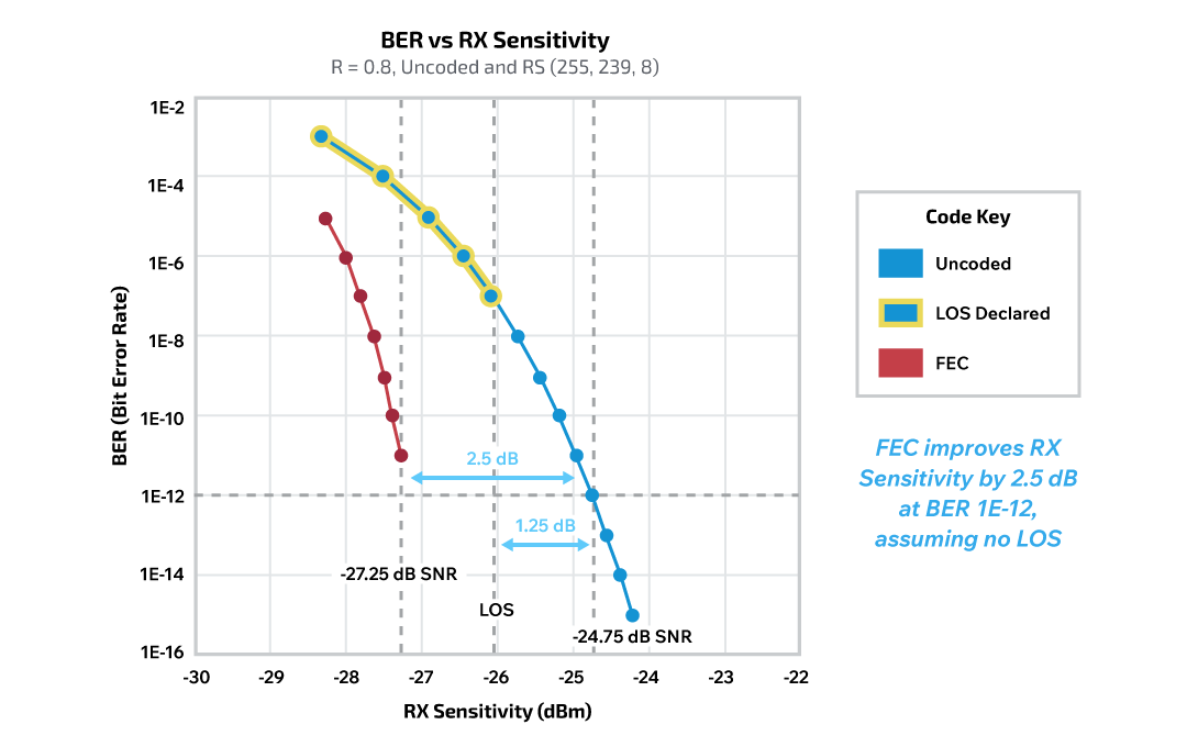
A potential issue with the optical receiver applications is that the optical receiver may declare loss of signal (LOS) at a signal receiver sensitivity level that is above the BER 10-4 performance level (uncoded). In this case, the LOS level becomes the limiting factor for FEC coding improvements, because the signal is lost well above the FEC performance limit. The graphs in Figure 4 show RX sensitivity versus BER for a system with uncoded BER 10-1 is achieved at RX Sensitivity -24.75 dBm. When the RX Sensitivity drops below this threshold, the BER degrades to about 10-7, and then LOS is declared. The addition of FEC will clean up the performance below -24.75 dBm RX sensitivity, but only for another 1.25 dB of sensitivity range before LOS is declared (at -26.0 dBm). The LOS prevents the system from enjoying the full 2.5 dB coding gain improvement in RX sensitivity.
FEC Decision Criteria in Aerospace Applications
As mentioned previously, aircraft often have optical fiber data path lengths of 30 meters or less and data rates of 1 to 25 Gbps. When the data rates are 1 to 2 Gbps, it is typically not worth implementing FEC coding. There are more cost-effective methods to improve BER such as using higher optical transmitter power, selecting a laser diode with a higher ER, selecting a photodiode with better sensitivity, selecting a better receiver amplifier, etc. Table 3 provides approximate E/N improvements that can be achieved by improving certain elements on the transmitter side, the fiber cable system, or the receiver side. One consideration for system improvement is that many times the system designer only has access to one of the system elements, either the transmitter, the receiver, or the cable system. In that case, the list of possible improvements is limited to what can actually be changed. The addition of FEC requires modification to both the transmitter and receiver side, and is typically more expensive than modifying a single performance element in the system, such as TX Power.
| Optical Subsystem Element | TX Side | Fiber Cable | RX Side | Typical Improvement, 1 Gbps MMF Link |
|---|---|---|---|---|
| Output Power | X | 3 dB | ||
| Extinction Ratio | X | 1 dB | ||
| Connector Losses | X | 2 dB | ||
| RX Sensitivity (TIA) | X | 2 dB | ||
| APD Diode | X | 5 dB | ||
| FEC | X | X | 2.5 dB |
Table 3: Link Budget Improvement by Optical Subsystem Element
When data rates are 10 to 25 Gbps, implementing FEC coding may be required to compensate for other SNR contributors in addition to the RX sensitivity limit. Some examples of SNR contributors present at 25 Gbps but not typically a factor at 1 Gbps include lower ER values from the modulator, higher RX amplifier input referred noise, and additional modal bandwidth limitations associated with multimode fiber. When optical link budgets are calculated for the higher speed 25 Gbps systems, these extra SNR contributors come into play.
Table 4 lists the major transceiver parameters that affect the optical receiver sensitivity and link budget. As shown in the table, the Input Referred Noise increases with higher data rates due to the higher bandwidth of the receive amplifier. The modulator Extinction Ratio is usually degraded (lower in value) as data rates become faster and laser rise/fall times can’t keep up. The laser TX Power is often a little higher for high data rate systems. RX Sensitivities can be calculated for 1-12 BER operation. The RX Sensitivity is derived from a SNR factor associated with 10-12 BER, a typical diode Responsivity of 0.5 A/W, the Input Inferred Noise from the table, adjusted by low ER power penalties from the table, and allowing for 3 dB implementation losses. The resulting Link Budget is simply the difference between the TX Power and the RX Sensitivity. As seen in the table, the lower data rates typically have good link budgets well above 10 dB, while the 25 Gbps link budget is only 7 dB unless FEC is employed to improve to 9.5 dB.
| Data Rate | Input Referred Noise | Extinction Ratio | TX Power | RX Sensitivity | Link Budget |
|---|---|---|---|---|---|
| 1 Gbps | 380 nA | 10 dB | -2 dBm | -18.5 dBm | 16.5 dB |
| 10 Gbps | 1400 nA | 5 dB | 0 dBm | -11.0 dBm | 11.0 dB |
| 25 Gbps | 2800 nA | 3 dB | +1 dBm | -6.0 dBm | 7.0 dB |
| 25 Gbps w/ FEC | 2800 nA | 3 dB | +1 dBm | -8.5 dBm | 9.5 dB |
Table 4:Common values of E/N degradation in fiber optic data transfer links
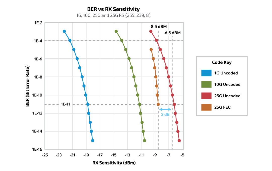
The graphs in Figure 5 plot BER values versus RX sensitivity for 1, 10, and 25 Gbps systems. The graph also shows how the addition of FEC improves the 25 Gbps system performance. In the 25 G uncoded case, the system needs an RX sensitivity of at about -6.5 dBm to achieve 10-11 BER performance. When FEC is employed, the RX sensitivity is improved by about 2 dB to a value of about -8.5 dBm to achieve the same 10-11 BER performance.
Modulation Schemes: From NRZ to PAM4 and the Need for FEC
Many of the early fiber optic links utilized a digital modulation scheme referred to as non-return to zero (NRZ), which has two levels per symbol and thus conveys one bit of information per symbol. The benefits of NRZ modulation include simplicity of implementation and good noise immunity. However, its main drawback is that it transfers only one bit of data per symbol. One of the primary limiting factors to increasing data transfer rates is that, when increasing the symbol transfer rate, it eventually exceeds the laser bandwidth or fiber modal bandwidth of the multimode system. By implementing the coding of multiple bits in one symbol, the data transfer rate for the system can be increased without the higher bandwidth of increasing the symbol rate and the data clock frequency.
One of the simplest improvements to NRZ modulation is pulse amplitude modulation 4 (PAM4). In PAM4, there are four levels per symbol and thus two bits of data are transferred in each symbol. More advanced modulation techniques employ greater numbers of amplitude and phase levels, but for this discussion, PAM4 is easy to understand and effectively demonstrates the main concepts.
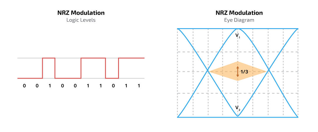
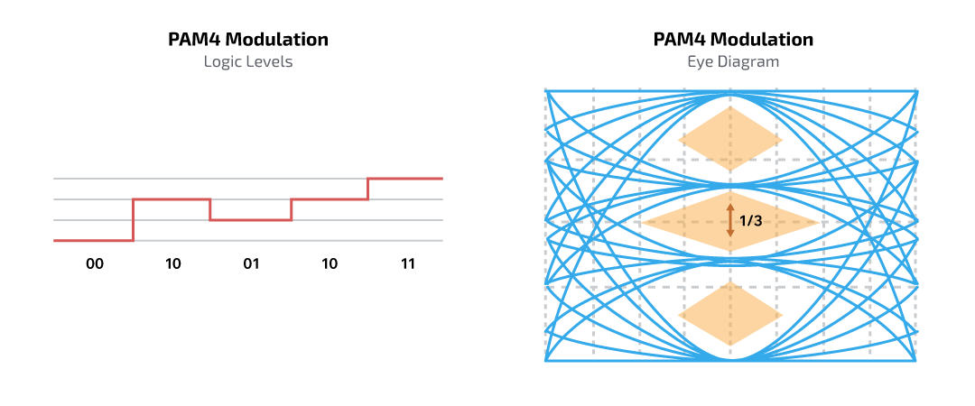
One key challenge in PAM4 implementation is that the amplitude of its logic levels are only one-third of those in NRZ modulation when maintaining the same symbol amplitude. The reduced logic level amplitude lowers the SNR of the system by 9.5 dB at 10-4 BER. If the noise levels of the receiving decoder circuits are not reduced, the BER of PAM4 will be significantly decreased relative to NRZ modulation. A 9.5 dB hit in PAM4 performance compared to NRZ often means that there are normally bit errors always present even without being anywhere near the RX sensitivity limits.
Reducing noise levels by redesigning and manufacturing new circuits can be costly; implementing FEC coding to decrease system bit errors to acceptable levels is often a more economical alternative. The diagrams in Figure 6A & 6B show the two logic levels and an eye diagram of NRZ modulation as compared to the four logic levels associated symbol eye diagram of PAM4.
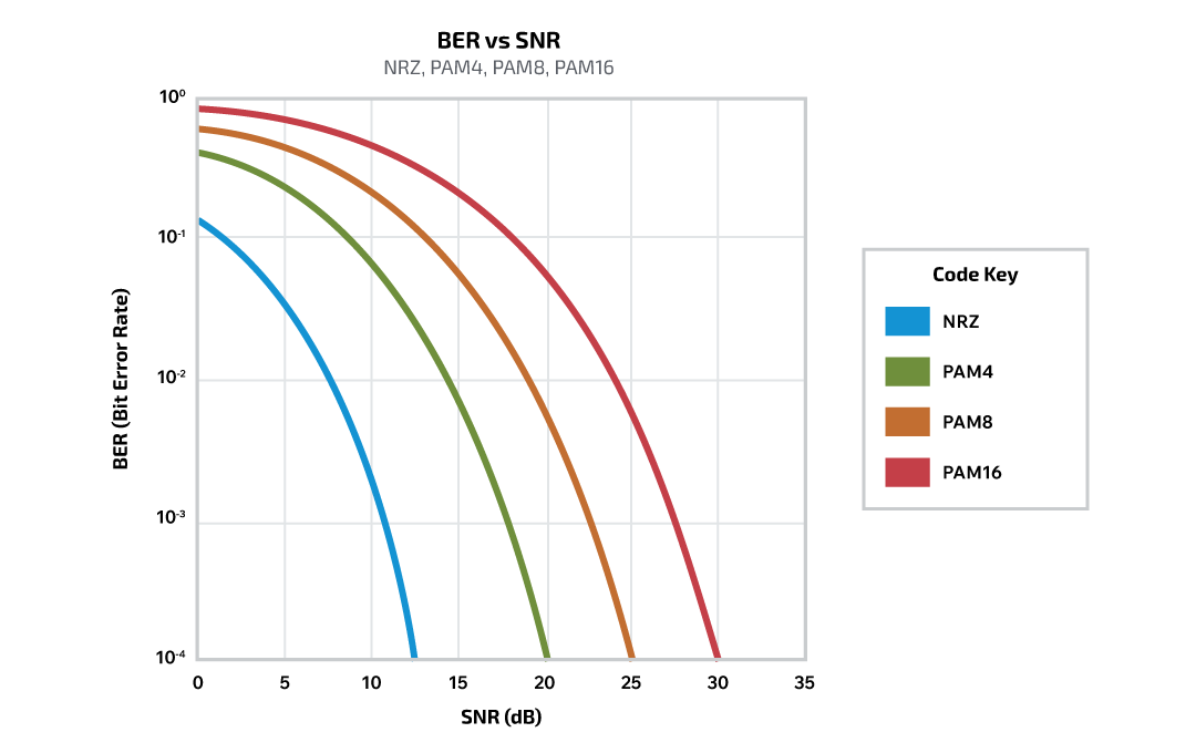
The graph in Figure 6C shows an increase in SNR to achieve the same BER performance as the number of pulse amplitude modulation levels increase from NRZ (2 levels) to PAM16 (16 levels).
Strategic Use of FEC in Modern Aerospace Systems
FEC is a proven technique for enhancing the performance of high-speed optical data links by enabling both error detection and correction. It has been instrumental in improving bit error rates in long-haul and bandwidth-constrained environments since its early adoption in the 1990s. In modern aerospace systems, where optical fiber lengths are typically short and operating data rates can reach 25 Gbps, the decision to implement FEC depends on system-specific trade-offs—particularly the nature of the noise sources and the required BER performance. While hardware upgrades may suffice for lower-speed links, FEC becomes increasingly valuable in mitigating signal degradation caused by inter-symbol interference, crosstalk, jitter, and bandwidth limitations, especially in systems using advanced modulation schemes such as PAM4.
For decades, Cinch Connectivity Solutions has supported defense and aerospace engineers with rugged, high-performance optical transceivers tailored to environments where reliability, low latency, and signal integrity are paramount. With deep expertise in fiber optic system design, Cinch continues to innovate in support of next-generation avionics and mission-critical data links. Engineers looking to evaluate the role of FEC in their system architectures can benefit from Cinch’s long-standing experience in optimizing optical link performance under demanding operational conditions.
 Optical Technology Connectors
 Optical Transceivers
 Media Converters