Understanding the Physics of Connecting High Frequencies
Radio frequency (RF) signals are essential to modern communication networks. This article is the second in a short series dedicated to explaining the physics behind RF transmission. The first part investigated the details of today’s most common RF cable types and explored the different options available to designers. This piece will focus not on cables but on the connectors that join them.
The Importance of RF Connector Performance
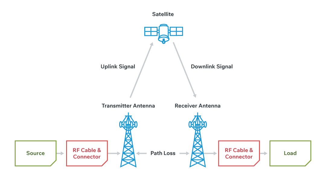
Coaxial and triaxial cables provide the physical channels that guide radio frequency (RF) signals from source to destination. For background on cable families and where each fits, see Selecting RF Cabling for Defense, Space, and Other Harsh Environments: Coax vs. Twinax vs. Triax. Yet a cable is only one part of the signal chain. Every run must interface with sources, filters, amplifiers, and antennas, and each interface is made through a connector. The overall system will perform only as well as the connectors that terminate and join these cable segments. In high-frequency designs, connectors are not simple terminations; they are part of the transmission line and must preserve the same electrical geometry and impedance as the cable.
Electromagnetic Wave Propagation in RF Systems
RF energy travels as an electromagnetic wave, not as a bulk flow of electrons. The signal’s energy resides in the electric and magnetic fields that occupy the space between the inner conductor and the outer conductor (shield), and those fields are contained by the shield. Efficient power transfer depends on the precise relationship between these conductors. The dielectric sets their spacing and contributes its permittivity—the ease with which an electric field forms—which together establish the cable’s characteristic impedance. Any interruption that disturbs this geometry, including a poorly designed or mismatched connector, will disturb the fields and degrade signal integrity. Standards such as IEC 62037, which governs passive intermodulation testing, ensure that connectors and cables maintain this integrity under real-world conditions.
Impedance Matching and RF Signal Integrity
The dielectric sets the spacing between the inner conductor and the shield and, together with the conductors’ geometry, determines the cable's characteristic impedance. Impedance is the opposition a circuit presents to time-varying signals; it combines resistance and reactance and is measured in ohms (Ω). For high-frequency designs, maintaining constant characteristic impedance through every transition is critical, so a connector must preserve the cable's electrical geometry—conductor diameters, dielectric profile, and contact transitions—through the signal path.
In direct current (DC) and low-frequency alternating current (AC) applications, a connector mainly needs secure metal-to-metal contact, and small dimensional variations seldom affect performance beyond contact resistance. At RF, the connector is part of the transmission line. Any discontinuity in geometry or materials introduces an impedance mismatch that reflects energy and degrades signal integrity, so connectors must be treated and designed as controlled-impedance components. This requirement is reinforced by MIL‑STD‑188, which specifies intermodulation performance for military satellite communications, and by ITU‑R S.465, which defines RF performance criteria for satellite earth stations.

Understanding Reflections, VSWR, and Power in RF Systems
Why Reflections Happen
RF transmission lines are designed for a characteristic impedance Z0 (e.g., 50 Ω). Whenever a wave on the line encounters a discontinuity—like a connector transition, a solder joint, or a load that isn’t exactly Z0—part of the wave reflects back toward the source. The strength of that reflection is captured by the reflection coefficient:
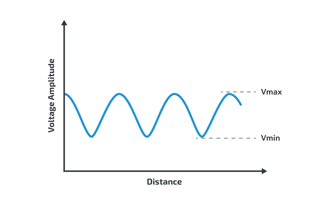
We typically work with its magnitude, |Γ|, which is the ratio of reflected to incident voltage at the discontinuity. The incident and reflected waves superimpose and create a pattern of voltage peaks and nulls along the line—i.e., a standing wave.
The Three Interchangeable Specs
Voltage Standing Wave Ratio (VSWR) is the ratio of the maximum to minimum voltage amplitudes along the transmission line, resulting from the standing wave pattern created by reflections. If there is no reflection at all, the standing wave does not form. The voltage is uniform along the entire length of the line, giving a VSWR of 1:1. However, as more energy is reflected, voltage variations along the line become more pronounced, and the VSWR increases. In some high-power systems, an excessively high reflection can cause damage to transmitters and amplifiers.
Voltage Standing Wave Ratio (VSWR):
Return Loss (RL):
Higher RL (more negative reflection in dB) means a better match.
You can move between them with the formulas above. Choose the one that matches your test setup or the standard you’re working to (antenna datasheets often use VSWR; many digital/serdes standards specify return loss).
What It Means for Power
Only a fraction of the forward power reaches the load when there’s a mismatch. The delivered-power fraction is:
The corresponding mismatch loss is:
This is the penalty you pay in the link budget purely due to impedance mismatch (separate from cable/connector insertion loss).
Why Manufacturing Precision Matters for RF Connectors
Connectors must therefore exhibit the same impedance as the cable to which they are mated, requiring precision in manufacturing that is beyond that required for most conventional connectors.
Passive intermodulation (PIM) is the name given to unwanted, spurious RF signals that are created in connectors and cables. As the name suggests, these are passive components, and so the unwanted signals are created purely by the interaction of signals with imperfections in the transmission line. This could be damage caused during the manufacturing process, or by factors as trivial as contamination or even loose connections. Because receivers often operate with very weak signals, they are highly sensitive to interference, and even low-level PIM can mask or distort critical data streams. These unwanted signals degrade overall signal quality, which reduces the sensitivity of the receiver. PIM is measured in dBc (decibels relative to the carrier).
| Cause | Description |
|---|---|
| Contaminated surfaces | Dust, grease, or debris on connector interfaces |
| Loose connections | Poor mating force or incomplete engagement |
| Manufacturing defects | Burrs, misalignments, or surface roughness introduced during fabrication |
| Material inconsistencies | Use of ferromagnetic or dissimilar metals |
| Corrosion or oxidation | Environmental degradation at contact points |
As PIM is created by physical irregularities, reducing PIM in connectors is a combination of sound design and precision manufacturing. The installation process also plays an important role, and adherence to best practices will help ensure a well-performing transmission line.
Minimizing Signal Power Loss with Low-Insertion-Loss Connectors
Both voltage standing wave ratio (VSWR) and passive intermodulation (PIM) impact the integrity of a signal within a transmission line, but they are not the only contributors to signal degradation. A critical yet often overlooked factor is insertion loss, which represents the reduction in signal power caused by the introduction of components—such as RF connectors—into the signal path.
Insertion loss is quantified in decibels (dB) and calculated using the formula:
where Pin is the input power and Pout is the output power after the signal passes through the component.
This loss combines resistive, dielectric, radiation, and mismatch losses, and becomes increasingly significant at higher frequencies due to greater skin effect and material dispersion.
Importantly, signal loss is cumulative—each interconnect or component adds incremental attenuation. Even a small insertion loss of 0.3 dB per connector can become substantial across multiple connection points in a system.
To preserve signal strength and ensure system efficiency, particularly in high-frequency applications such as 5G and radar, the best RF connectors are engineered to maintain insertion loss as close to 0 dB as possible. Precision manufacturing, optimized materials, and impedance matching are key design features that help minimize insertion loss.
Selecting the Right RF Connector for High-Frequency Applications
The selection of the right connectors for high-frequency applications is therefore a careful balance of several key characteristics, many of which are unique to the RF arena. The connector must perform well over the required operating frequency, and the characteristic impedance must match that of the rest of the transmission line.
| Connector Type | Max Frequency (GHz) | Strengths / Notes |
|---|---|---|
| 1.0 mm | 110 | Ultra-high frequency, precision measurements, excellent for mmWave test equipment |
| SMP3 | 50 | Compact, blind-mate, widely used in aerospace and defense |
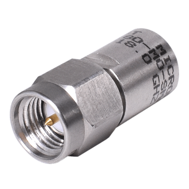
| SMA | 18 | Widely used, threaded coupling, durable, common in antennas and radar |
| SMC | 10 | Small, threaded coupling, cost-effective for lower-frequency RF applications |
In addition to frequency range and connector style, the design of the connector must also be capable of handling the required power levels without overheating or arcing. This leads directly into a set of broader selection criteria that engineers should keep in mind when choosing the most appropriate connector for their system.
Key Selection Criteria for RF Connectors:
- Match connector impedance to transmission line (e.g., 50 Ω or 75 Ω)
- Ensure performance across the full operating frequency range
- Confirm power handling capability for system requirements
- Select materials with suitable thermal and electrical properties
- Verify mechanical durability under expected environmental stress
- Check availability of mating cycles and ease of installation
These electrical requirements must be matched with mechanical reliability. Modern applications frequently require cables and connectors to function in tough conditions. The rapid growth of 5G connectivity has seen more need for fixed infrastructure. The higher frequencies used in 5G are more sensitive to path loss and interference from obstructions, which means that cell sizes are smaller. A smaller cell footprint requires a greater density of base stations, and these are often installed in tough environmental conditions including wind, rain, and exposure to sunlight.
RF Connector Durability in Harsh Environments
The defense and aerospace sectors have always been at the cutting edge, demanding high performance systems that work in extreme conditions. Millimeter wave (mmWave) technology, using frequencies above 30 GHz, is becoming common in satellite communications, guidance, and Electronic Countermeasures (ECM) applications. The short wavelength allows the use of very small antennas and highly directional beamforming, opening many opportunities for miniaturized systems.
As frequency is increased, wavelengths become smaller. This means that the efficient transmission of higher frequencies requires RF cable sizes that are optimized for the shorter wavelength. This may involve smaller diameters, which in turn creates the need for smaller connectors that are manufactured to high levels of precision.
Matching Connector Performance to Application Demands
Selecting the right RF connector is a unique challenge. Unlike many conventional applications, high frequency transmissions demand more than just mechanical reliability and efficient electrical connection. Selecting these connectors requires a thorough understanding of the physics at work to carefully evaluate the connector’s characteristics.
Explore Bel’s full range of high-performance RF connectors, designed to deliver maximum signal integrity and reliability for the latest high-frequency systems.
 RF and Microwave Cable Assemblies
 RF & Microwave Connectors
 RF & Microwave Terminations