
In defense and aerospace programs, a connector cannot be serviced in the field, repaired at altitude, or replaced once a platform is in orbit. With operating conditions that often include extreme vibration, rapid temperature swings, pressure changes, and corrosive atmospheres, connector reliability needs to be an absolute certainty.
This is the purpose of qualification testing. It provides physical proof, under controlled and documented conditions, that a specific part will survive the program environment. This article explains how that testing is structured, what it takes to sustain it, and what to look for when evaluating connector suppliers.
The QPL Baseline
The Qualified Parts List (QPL) is the formal mechanism through which the U.S. Defense Logistics Agency (DLA) certifies that a connector, manufactured by a specific supplier at a specific facility, has passed the qualification test sequence defined by the relevant military specification. Earning and maintaining QPL status is an ongoing commitment, suppliers re-test on a regular cycle, typically every three years, and must keep passing DLA audits.
QPL status matters because it transfers qualification risk away from the customer. When a program engineer specifies a QPL‑listed connector, they can rely on:
- The supplier’s successful completion of the full qualification test sequence
- The supplier’s ongoing surveillance audits under MIL‑STD‑790
- The supplier’s obligation to requalify on a defined cycle
This allows program teams to avoid re‑running the MIL-SPEC test sequence themselves, a cost and schedule burden that becomes significant for high‑reliability platforms.
How a Supplier Earns QPL Status
Qualification begins with a test plan. For a given MIL-SPEC, the test plan defines which connector configurations will be tested, what tests will be run in what sequence, and what the pass/fail criteria are. The test plan is organized into groups: Group 1, Group 2, Group 3, and so on, each specifying a set of tests that parts in that group must complete in order.
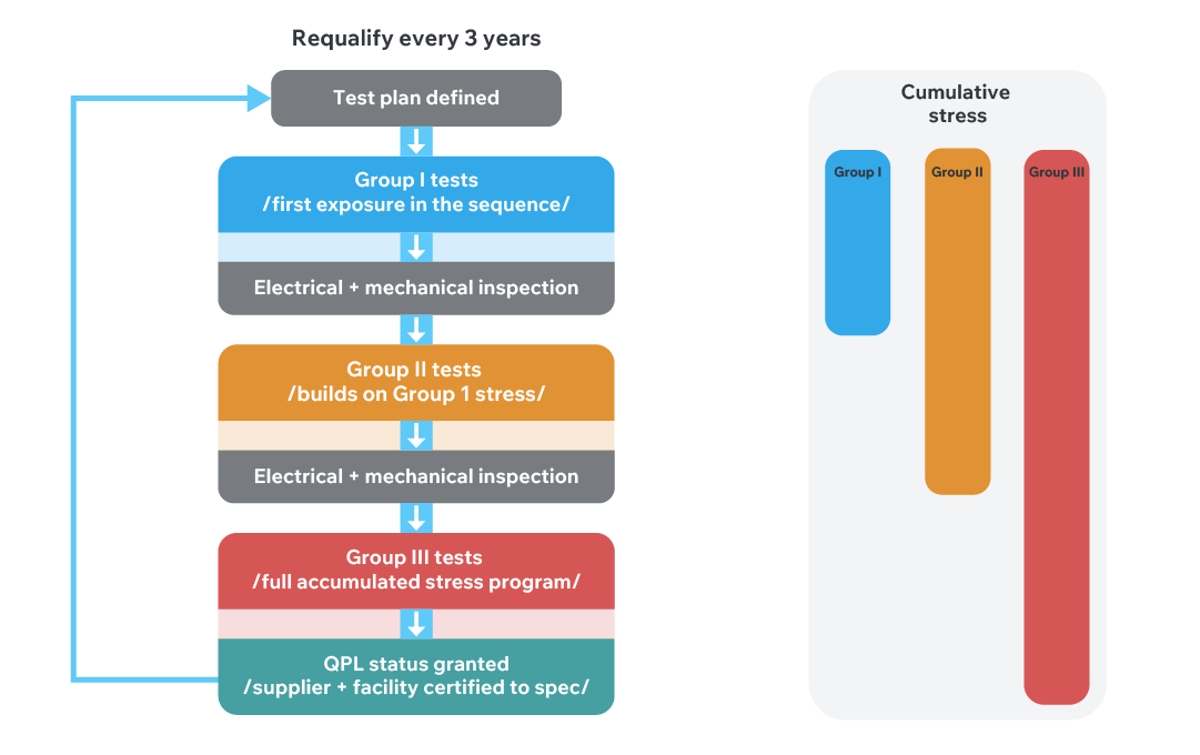
The test sequence is not a checklist. It is cascading by design. Parts that pass one test move on to the next test within their group, accumulating stress as they go. Electrical and mechanical inspections are conducted between tests throughout the sequence. After vibration testing, for example, parts are evaluated for electrical continuity and mechanical integrity before the next stress is applied. The qualification authority requires that parts be exposed to the full sequential stress program, not just to individual tests in isolation.
The Base Document and Slash Sheet Structure
Each MIL-SPEC functions as a base document defining the general qualification framework. Specification sheets (slash sheets) define precise performance parameters for individual connector variants: dielectric withstanding voltage levels, insulation resistance minimums, mating cycle counts, temperature ratings, and other performance criteria that vary between connector families. When a program engineer specifies a connector to a slash sheet, they are specifying to a defined and tested performance baseline.
AS 9100: The Quality Management Backbone
QPL test results do not exist in a vacuum. A connector that passes the qualification test sequence in one manufacturing run can fail to deliver the same performance if the manufacturing process is not controlled, documented, and auditable. The quality management framework that gives customers confidence in manufacturing consistency across facilities, across years, and across order volumes is AS 9100 Rev D.
AS 9100 is an aerospace-specific extension of ISO 9001. Where ISO 9001 covers a supplier's overall quality management system, AS 9100 adds requirements specific to aerospace and defense: risk management processes, configuration control and revision management, First Article Inspection (FAI) requirements, and production process surveillance that ensure the process currently producing parts is the same documented and validated process that produced the qualification samples.
AS 9100 certification also substantially streamlines the DLA surveillance audit process for qualified suppliers. Defense auditors know which AS 9100 records to request, and a supplier with a mature AS 9100 implementation is in a position to respond to those audits efficiently. Defense customers may also conduct their own supplier audits, ranging from a focused review of a specific process area to a comprehensive audit that mirrors the AS 9100 scope in full.
What the Testing Covers
Qualification testing falls into three categories: mechanical, electrical, and environmental.
| Category | Main Tests | What It Confirms |
|---|---|---|
| Mechanical | Vibration, Shock, Durability | The connector holds up under movement and across a service life of mating cycles. |
| Electrical | Dielectric Withstanding Voltage, Insulation Resistance, Low-Level Contact Resistance | The insulation will not break down under voltage, is not leaking current, and the contacts are clean. The life test ages the part quickly to reveal slow-developing problems. |
| Environmental | Moisture, Salt Spray, Temperature Cycling | The connector recovers its performance after moisture exposure, resists corrosion, and handles repeated heating and cooling without seals or contacts failing. |
Table 1: Qualification Test Categories and Requirements
Mechanical Tests
Shock and vibration testing addresses two distinct loading conditions:
- Vibration: continuous shaking across a defined range of frequencies and intensities. It simulates the steady, real‑world motion a connector experiences during flight.
- Shock: a single, high‑energy jolt with a specific force‑over‑time profile. It represents sudden events like stage separation, hard landings, or weapons firing.
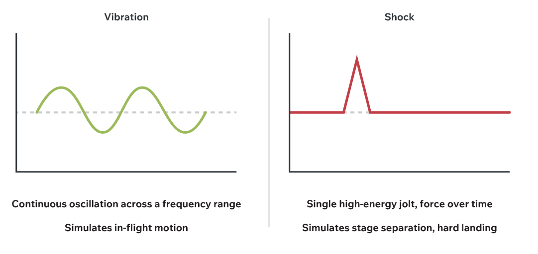
Both test types are governed by MIL-STD levels defined in the relevant specification.
The physical requirements for shock and vibration test equipment (floor loading, slab isolation, structural separation from occupied areas) along with occupational health considerations associated with the extended operation of high-energy vibration systems, make in-house installation undesirable for most manufacturing facilities. Cinch routes shock and vibration testing to qualified external test labs, which must themselves be qualified under DLA requirements.
Mechanical testing also evaluates the durability of a connector under the mating and unmating cycles that accumulate over program service life. MIL-DTL-83513, for instance, specifies 500 mating cycles. After the prescribed number of cycles, the connector is evaluated for electrical performance and mechanical integrity.
Electrical Tests
Dielectric Withstanding Voltage (DWV) testing applies a defined voltage between contacts, or between contacts and the connector shell, to verify that the insulating material will not break down under electrical stress. As an example, the MIL-SPEC baseline for MIL-DTL-83513 is 600V RMS.
Insulation Resistance (IR) testing measures the electrical resistance between contacts and between contacts and the shell, confirming that the insulating material is not conducting. 5000 megaohms is a common rating for different MIL-DTL part number families. IR measurement is a sensitive indicator of insulator condition and is an inspection checkpoint throughout the qualification test sequence.
Low-Level Contact Resistance (LLCR) measures the resistance of mated contact pairs at low signal current levels, specifically at current levels too low to generate self-heating at the contact interface. This isolates the measurement to the contact surface condition and the wipe mechanism function, independent of resistive heating effects that would confound the measurement at higher currents. LLCR is both a standalone test and an in-sequence inspection checkpoint.
The life test runs parts under electrical load, at rated current and elevated temperature, for 1,000 hours, approximately 42 days of continuous operation. The purpose is accelerated aging: exposing the connector to the degradation mechanisms that accumulate over operational service life in a compressed timeframe. Failure modes that would not appear in a single-event test sequence (contact surface oxidation, insulator creep, seal relaxation) can manifest under sustained thermal and electrical stress.
Environmental Tests
Moisture resistance testing runs parts through controlled temperature and humidity cycling over approximately two weeks. The evaluation criteria is not whether moisture enters the connector, it will. The criteria is whether the connector recovers full electrical performance when returned to a normal atmosphere.
Salt spray testing exposes connectors to a salt fog environment. Evaluation criteria are finish- and application-specific. Some programs require no visible corrosion on any surface. Ohers permit corrosion in defined non-functional areas.
Temperature cycling evaluates the effect of repeated thermal expansion and contraction on contacts, insulating materials, and seals. Cycle ranges, number of cycles, and rate of change are all defined in the MIL-SPEC and applicable slash sheets. Thermal cycling is a particularly sensitive test for hermetically sealed connectors, where differential expansion between dissimilar materials at a sealed interface can degrade leak performance over time.
Hermetic Sealing
For applications requiring hermetic sealing, connectors may be qualified to hermetic leak rate requirements in addition to the standard electrical, mechanical, and environmental test sequence. Two primary hermetic technologies are used:
- Epoxy hermetic sealing for applications where moderate leak rate performance is acceptable.
- Glass-to-Metal hermetic sealing where tighter seal performance and lower achievable leak rates are required.
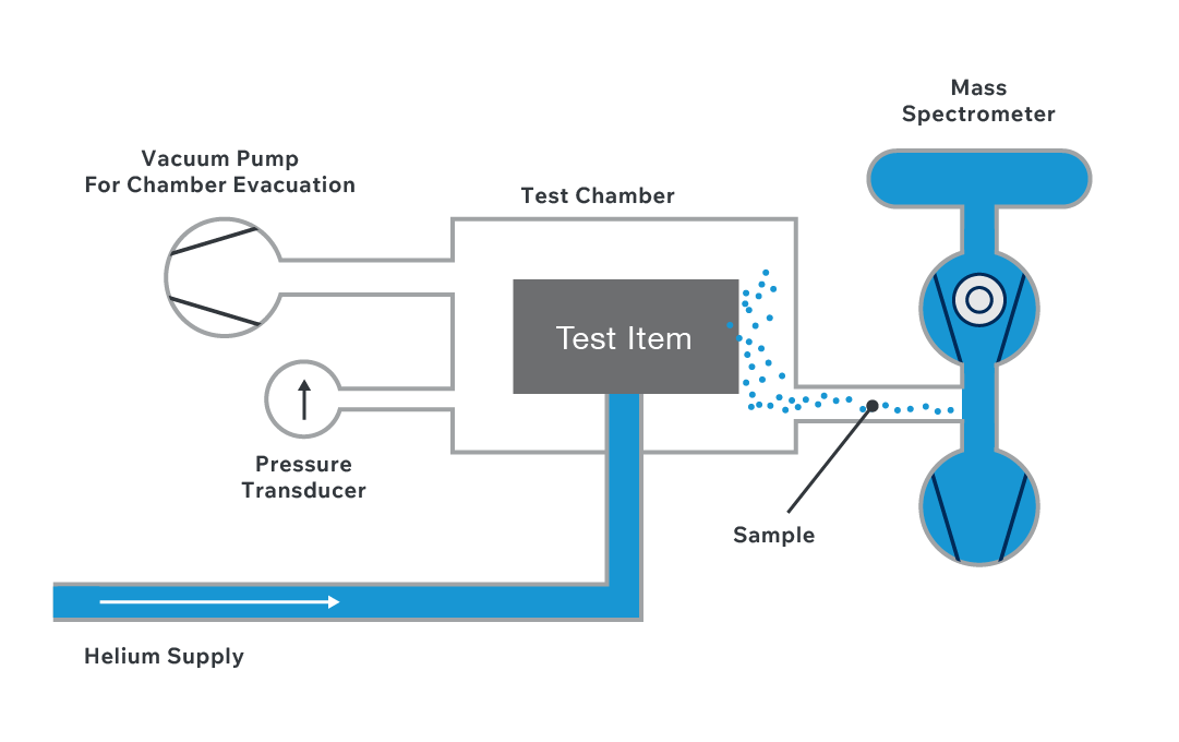
Hermetic leak rate testing uses helium as the test gas. Helium, as the smallest stable inert molecule, will escape through any seal pathway that would leak under worst-case operating conditions, making it the most sensitive practical indicator of seal integrity.
Cinch's Test Infrastructure
The practical value of in-house test capability is flexibility. A customer program presenting a non-standard test requirement—an elevated test level, a custom subgroup structure, a sequence that deviates from the QPL baseline—needs a supplier who can run that work without negotiating with a third-party test house and accepting their schedule. Cinch's primary internal test facility is the Lombard laboratory, with additional test capabilities across Cinch's manufacturing facilities.
When a program engineer works with Cinch on a non-standard test sequence that work can be executed internally. The documentation, inspection checkpoints, and chain of custody for qualification samples all remain under Cinch's direct control.
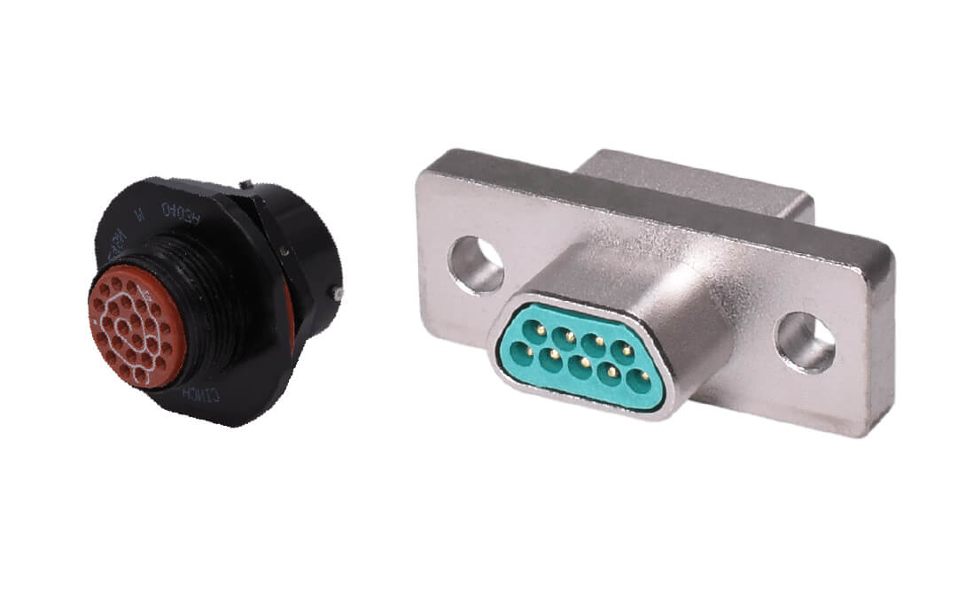
In-house capability also enables responsive support for OEM and custom product qualification, not only QPL maintenance. The same laboratory infrastructure that sustains QPL certification cycles also supports customer-specific qualification programs that require connector configurations not covered by an existing QPL line.
What This Means for Engineers Specifying Today
QPL is the floor, not the ceiling. Programs frequently need more than the baseline. Those requirements can include:
- More Demanding Tests - higher voltage for altitude, additional vibration profiles, specific salt-spray configurations, or wider temperature ranges, all agreed and documented in advance.
- Customer-Defined Requirements - in new applications where QPL coverage is limited or absent, customers define their own requirements from the ground up. Cinch has recent, direct experience translating system needs (temperature, vibration, altitude, outgassing) into connector specifications and then qualifying to them.
- Ruggedized Options - a step above standard catalog parts without the full cost and compliance overhead of QPL, positioned between the two.
For programs pushing beyond the standard QPL framework, new space customers defining requirements from system-level needs, programs requiring ruggedized catalog performance without full QPL overhead, or applications requiring hermetic sealing at specific leak rates, the supplier's experience with requirements definition matters as much as their product catalog. A supplier who has done this work before, documented it in a form that stands up to customer technical review, and delivered qualification data that programs have accepted is a different proposition from one encountering the process for the first time.
Cinch’s combination of engineering depth, in‑house test capability, and long-standing industry experience makes them a supplier engineers can rely on, both to meet the QPL baseline and to deliver the elevated, mission‑specific qualifications that many defense and aerospace programs now require.
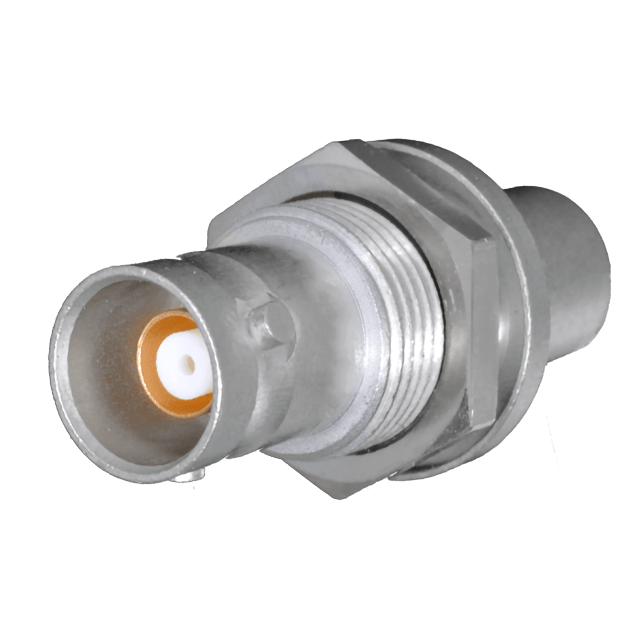 Space-Rated RF & Microwave Connectors
 Mil-Spec Qualified Circular Connectors
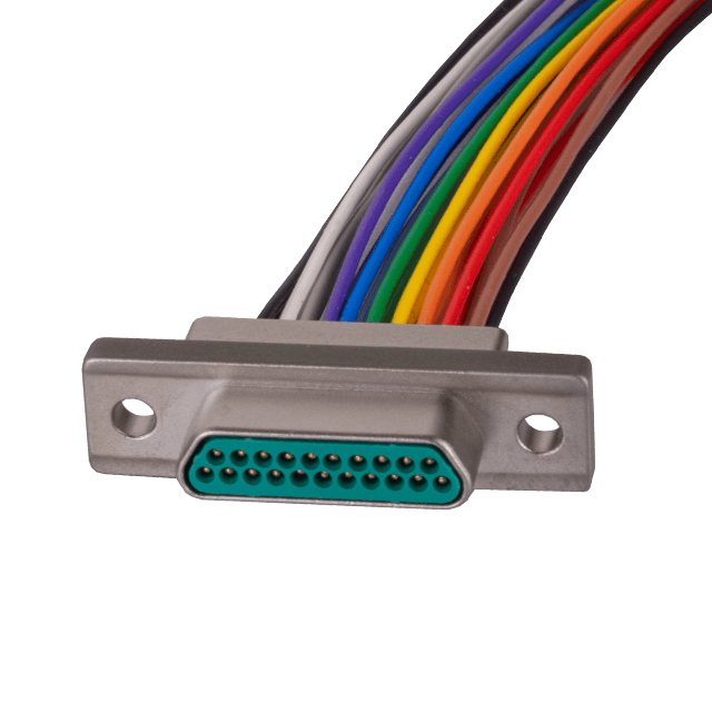 Space-Screened Micro-D Connectors